Timber Engineering Calculator contains 55 Calculators for different Timber and Civil Engineering parameters.
Comprehensive Calculator for Timber and Wood-works.
*** Available in Metric (SI) and Imperial (USCS) Units ***
• Area of Section (Rectangular and Square Beam)
• Moment of Inertia (Rectangular and Square Beam)
• Distance from Axis to Extremities of Section (Rectangular and Square Beam)
• Radius of Gyration (Rectangular and Square Beam)
• Section Modulus (Rectangular and Square Beam)
• Maximum Fiber Stress (Rectangular Timber Beam)
• Maximum Fiber Stress using Section Modulus (Rectangular Timber Beam)
• Horizontal Shearing Stress (Rectangular Timber Beam)
• Horizontal Shearing Stress (Rectangular Timber Beam with a notch in the lower face at the end)
• Modified Total End Shear (Concentrated Loads)
• Modified Total End Shear (Uniform Loading)
• Allowable Unit Stress on Timber Columns (Single Piece of Lumber/Group of Pieces glued together)
• Allowable Unit Stress on Timber Columns (Square/Rectangular Cross Section)
• Allowable Unit Stress on Timber Columns (Circular Cross Section)
• Allowable Unit Compressive Stress (Load is at an angle to the grain)
• Allowable Stress - Rectangular Section (National Design Specification)
• Allowable Compressive Stress inclined to grain (Hankinsons Equation)
• Extreme-Fiber Bending - Adjusted Design Value
• Tension - Adjusted Design Value
• Shear - Adjusted Design Value
• Compression perpendicular to the grain - Adjusted Design Value
• Compression parallel to the grain - Adjusted Design Value
• End grain in bearing parallel to the grain - Adjusted Design Value
• Modulus of Elasticity - Adjusted Design Value
• Size Factor
• Volume Factor (Southern Pine)
• Volume Factor (Other Species)
• Radial Stress induced by a Bending Moment
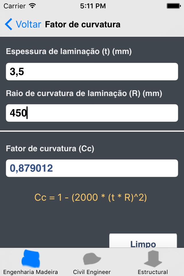
• Curvature Factor
• Bearing Area Factor
• Slenderness Ratio for Beams
• Allowable Withdrawal Load (Nails and Spikes penetration)
• Total Allowable Lateral Load - Group I Wood (Nails and Spikes penetration)
• Total Allowable Lateral Load - Group II Wood (Nails and Spikes penetration)
• Total Allowable Lateral Load - Group III Wood (Nails and Spikes penetration)
• Total Allowable Lateral Load - Group IV Wood (Nails and Spikes penetration)
• Allowable Withdrawal Load (Threaded portion of a Wood Screw penetration)
• Total Allowable Lateral Load - Group I Wood (Wood Screws penetration)
• Total Allowable Lateral Load - Group II Wood (Wood Screws penetration)
• Total Allowable Lateral Load - Group III Wood (Wood Screws penetration)
• Total Allowable Lateral Load - Group IV Wood (Wood Screws penetration)
• Bolts - Adjusted Design Value for Lateral Loading
• Split-Ring and Shear-Plate Connectors - Adjusted Value for Loading Parallel to Grain
• Split-Ring and Shear-Plate Connectors - Nominal Value for Loading Normal to Grain
• Nails and Spikes - Adjusted Design Value for Withdrawal
• Nails and Spikes - Adjusted Design Value for Lateral Loading
• Wood Screws - Adjusted Design Value for Withdrawal
• Wood Screws - Adjusted Design Value for Lateral Loading
• Lag Screws - Adjusted Design Value for Withdrawal
• Lag Screws - Adjusted Design Value for Lateral Loading
• Metal Plate Connectors - Adjusted Design Value for Lateral Loading
• Drift Bolts and Drift Pins - Adjusted Design Value for Withdrawal
• Drift Bolts and Drift Pins - Adjusted Design Value for Lateral Loading
• Spike Grids - Adjusted Design Value for Lateral Loading
• Stress and Deflection Factor (Ponding)


